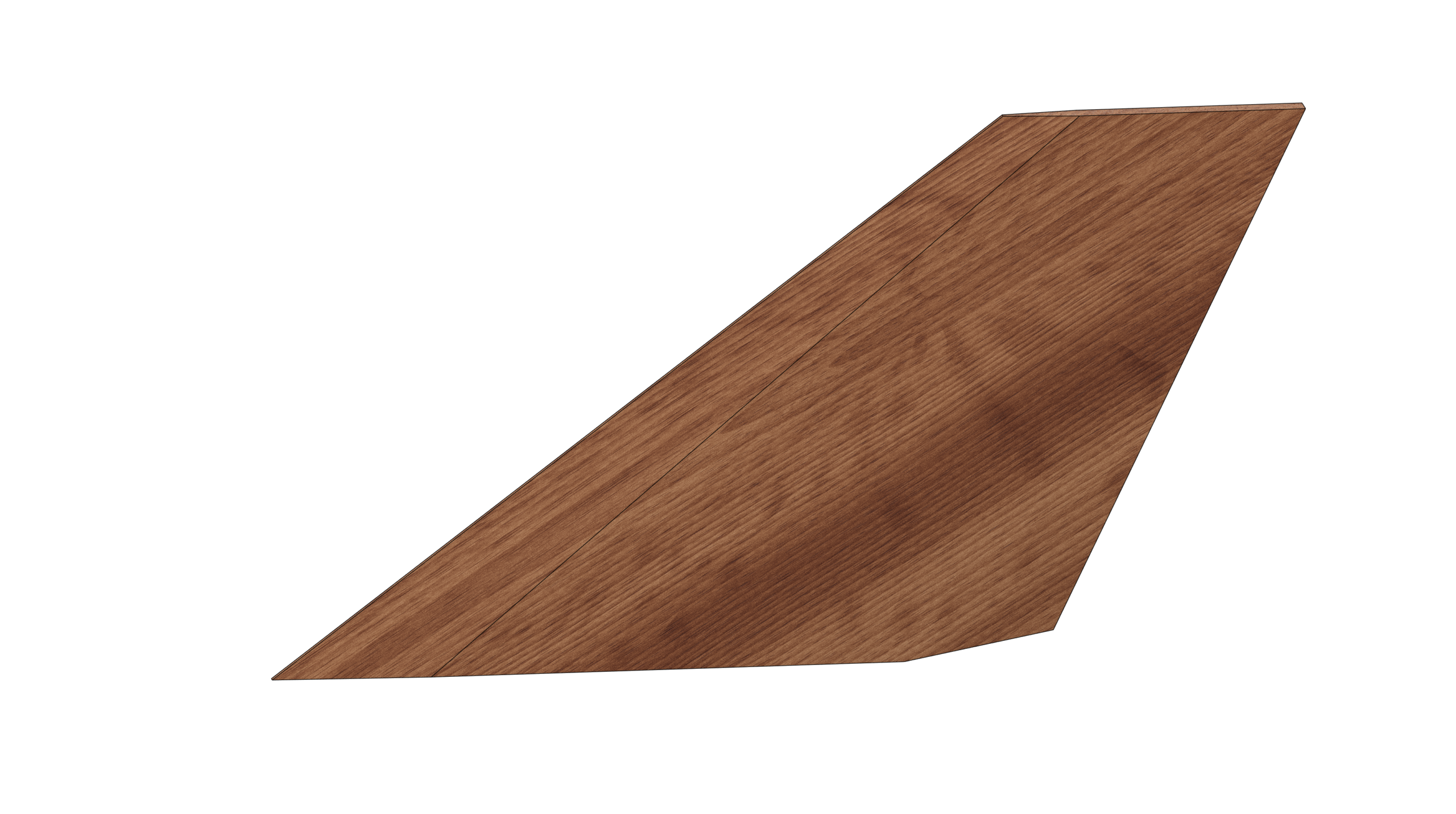
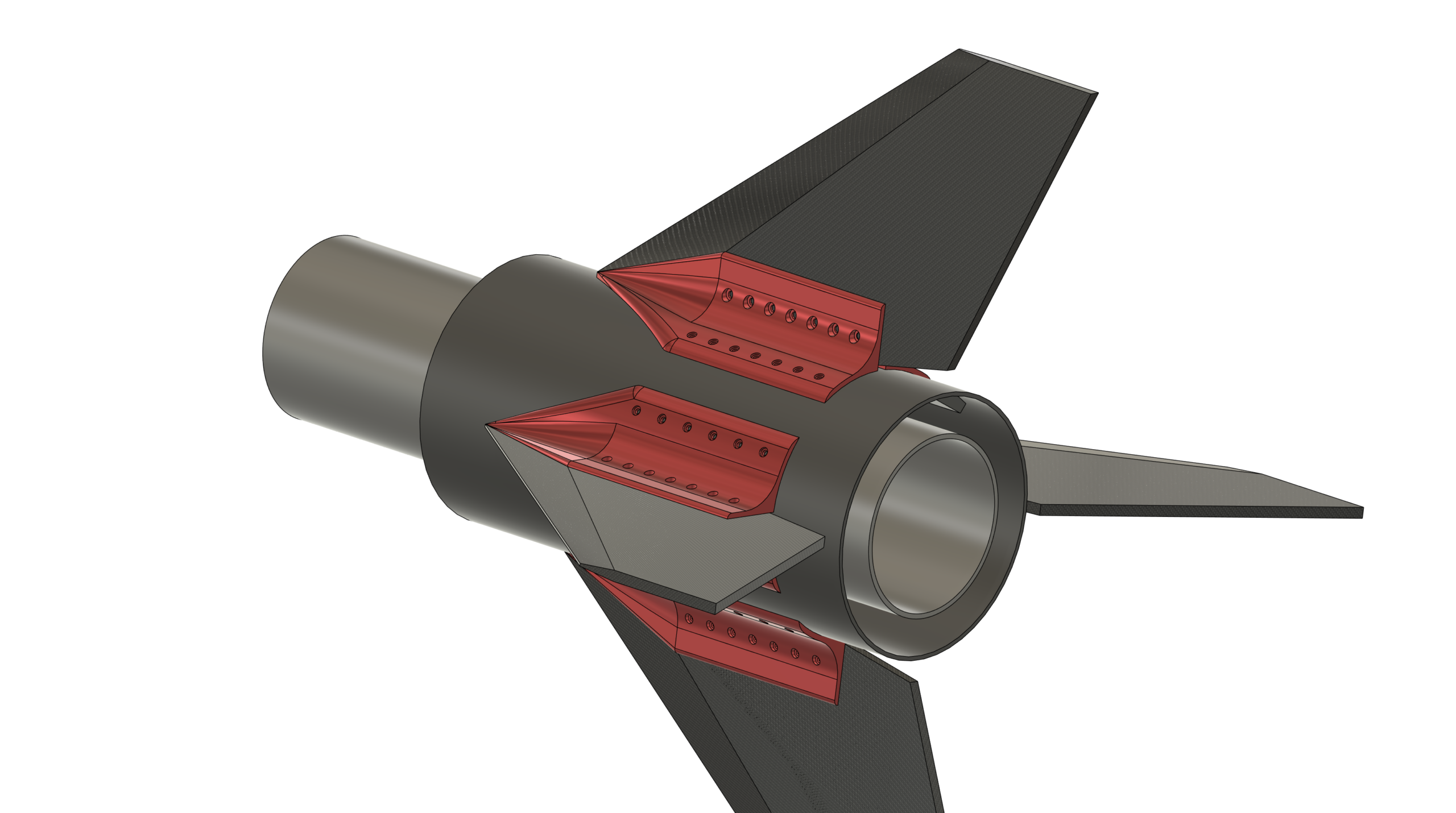
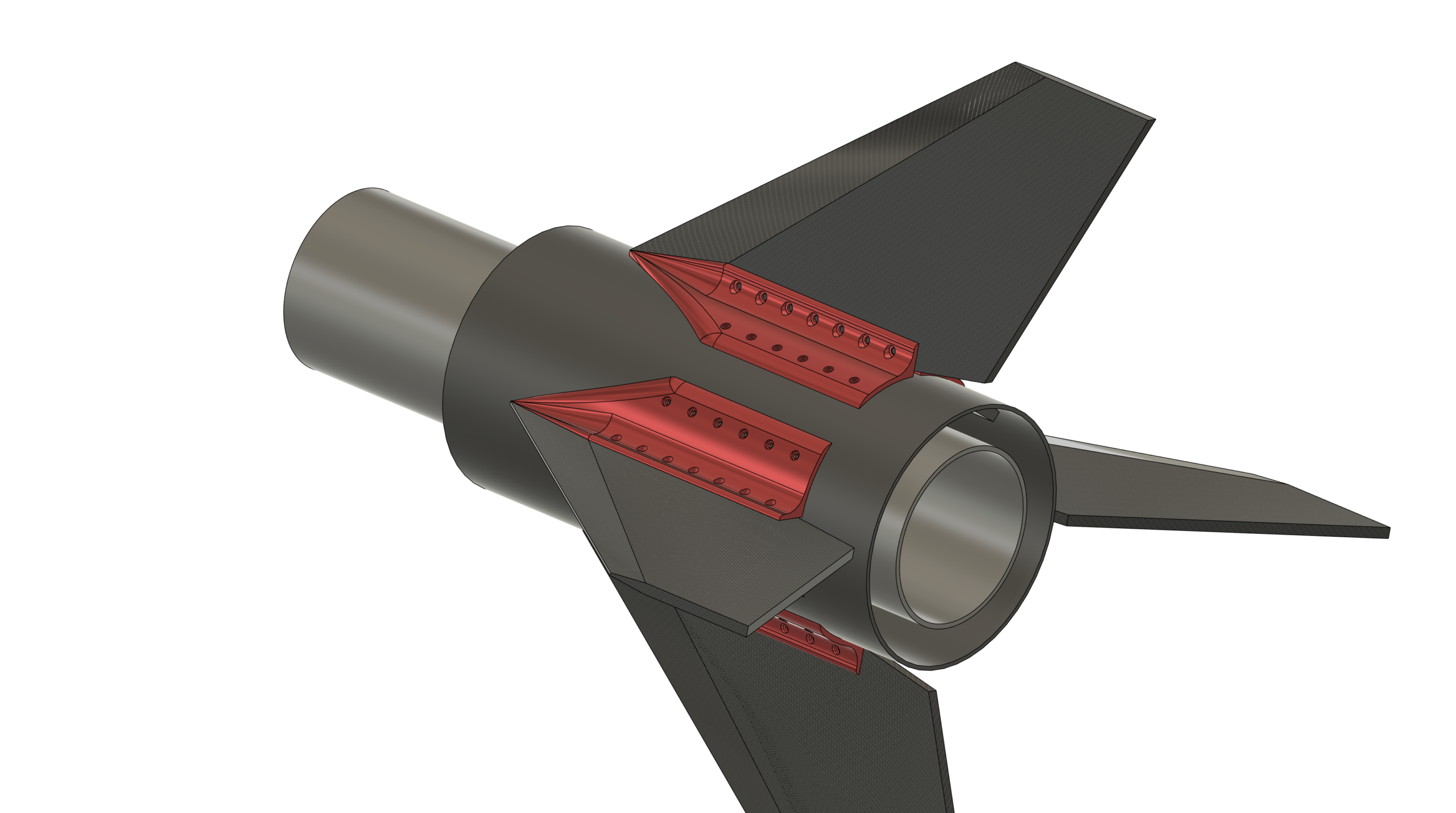
Fin Profile Design Choice: Swept Delta was chosen based on team feedback
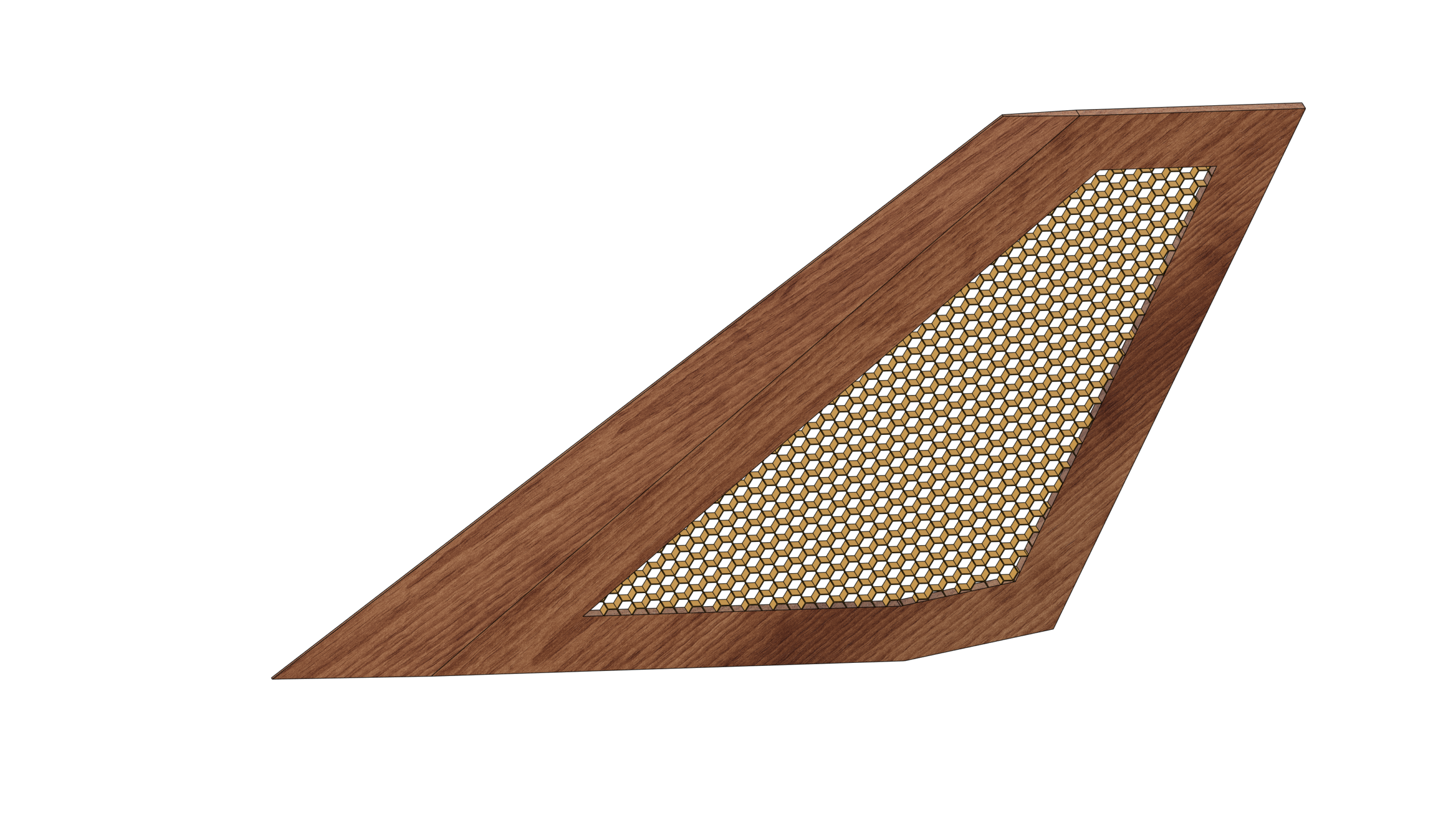
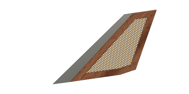
Construction Design Choice: Core concept of the proposed design is to construct the fins from a combined Birch Play and Nomex Honeycomb laminate. The Birch Play would form the outside edges and the honeycomb would be added to the center of the fins. The purpose of the Birch ply would be to provide additional strength for:
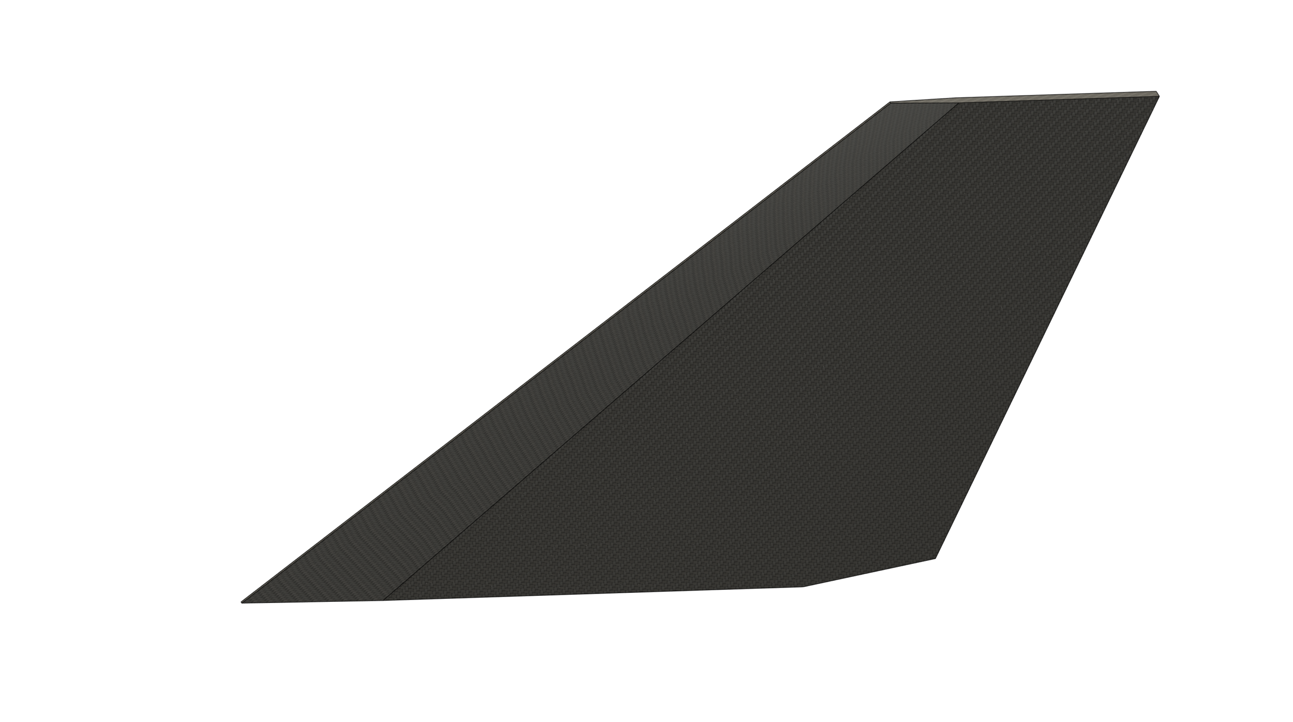
This Birch ply / Honeycomb combination will then be laminated with either fiberglass or carbon fiber.
You could ask: This seems overly complicated – why not just use solid Birch ply fins?
— This is true and will make the fin construction a lot simpler. You could argue that the honeycomb would make the fins lighter and that is also true – but the counter to this is that the slight weight saving is negligible relative to the overall rocket weight which is significant.
The main objective of this design is to encourage group participation where we can explore different construction techniques, and everyone can contribute and learn.
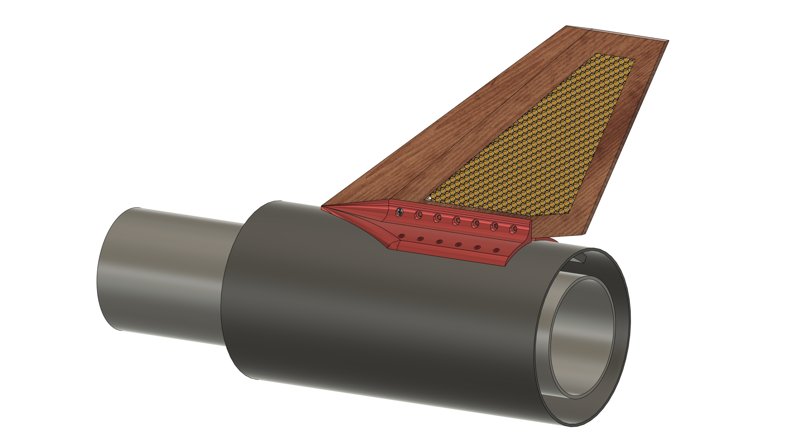
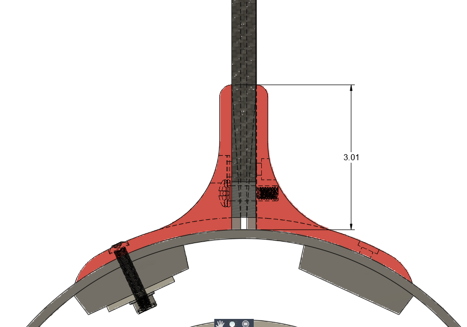
The concept is that we use the existing internal stringers as ‘supports’ for the 1/4″-20 bolt/nut combination that will bolt the brackets to the airframe.
We will add an 1/8″ aluminum backing plate that spans the length of the internal stringers to distribute the clamping forces and point loads introduced by the bolts. This should eliminate the potential for shearing and also prevent the fiberglass airframe from cracking under load.
I have designed the aluminum brackets to have a wide as possible ‘footprint’ where the brackets contact the fiberglass airframe – this wide footprint should distribute the clamping load as much as possible.
Question: With a root of the fins being plywood, do you think the brackets need to extend taller adjacent to the fin to impart more rigidity?
Answer: It should be as tall as possible but this is where I run into depth constraints on the mill… I need to be able to reach down into the negative space to remove material and not crash the holder into the sides. Unless I run a longer / taller endmill but that will result in chatter which in turn can be combatted by running smaller depth of cuts and cutting speed. Problem is that will increase the cycle times and with the 8x multiplier this becomes a problem. So short answer is: what we have is optimal bracket design.
The bracket / fin interface size has been increased from 1.5inches to 3inches. This will create a larger clamping surface area to aid in overall strength and stiffness, especially since we are clamping laminated wood fins vs. aluminum.
An alternative could be where the fin leading edge is machined from aluminum and then integrated into the Birch/Nomex fin body with a ‘tongue and groove’ interface.
This can be considered as the project progresses based on time and resource availability.
At face value this looks like it should be a relatively simple CNC machining operation BUT the size of these leading edges will make this really tricky and time consuming. Figuring out the work holding strategies for the second side operation will also not be trivial.
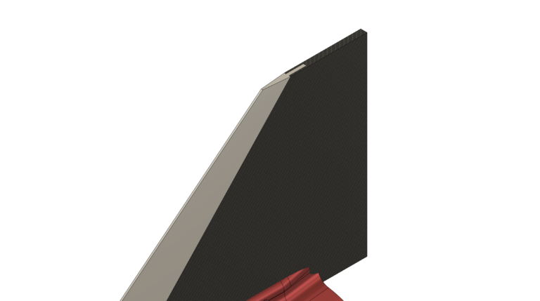
How to bevel the fin leading edge? The size of the fins makes this a tricky problem that we need to solve as a team.
In the past I have used a table saw to cut fin bevels and that is relatively easy when working with standard fin sizes.
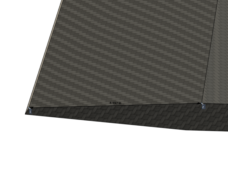
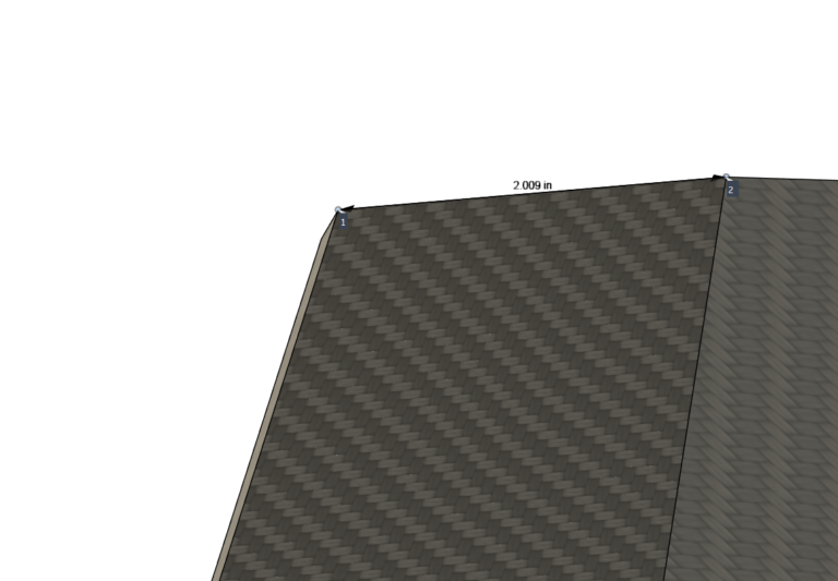
The problem we face is that the fin bevels run from ~4 inches at the bottom to ~2 inches at the top and my standard table saw blade only extends to ~3inches.
Not going to solve this here but we will need to come up with a way to do this accurately.
IF we were to opt for the above mentioned “Stretch Goal” using aluminum for the leading edges then these ALU strips will be machined on the CNC mill.
Team Meeting | We will schedule a team meeting to discuss the proposed design and construction concepts. Date / Time TBD |
3D Print a set of brackets | Jack will 3D print a set of the brackets on the Club Giga-Printer. This will give us a sense of the airframe fit and just help visualize the overall design. |