No ‘traditional’ Motor Mount Tube |
|
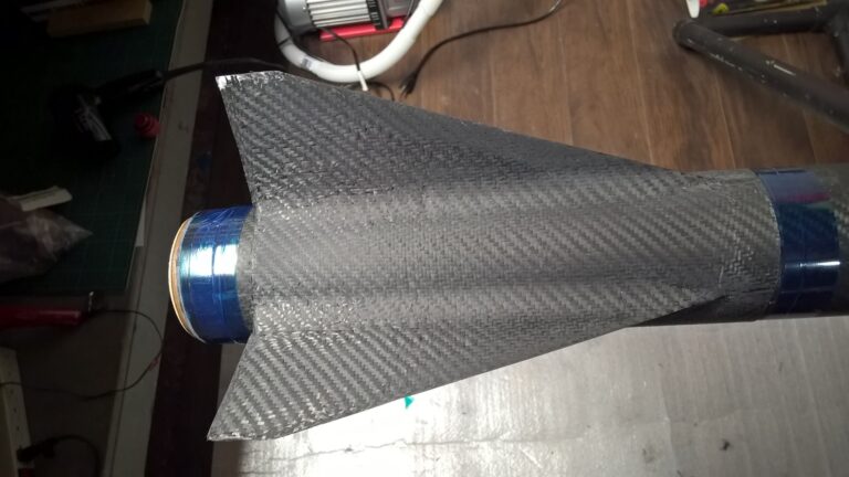
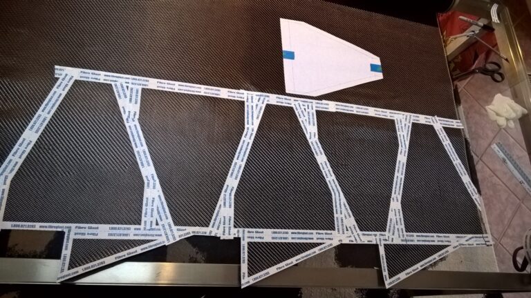
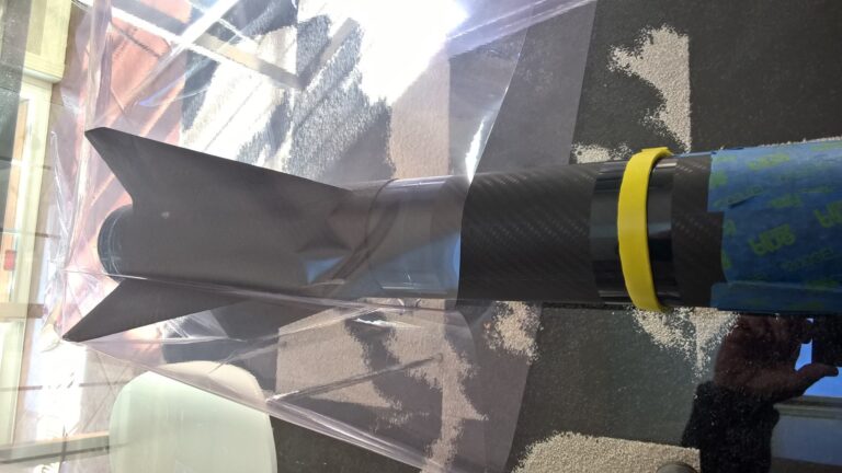
Description | Fins are directly mounted on the airframe, and the four fins are aligned at 90 degrees |
Additional Support / Strength | Filler infused epoxy fillets ONLY |
Comments |
|
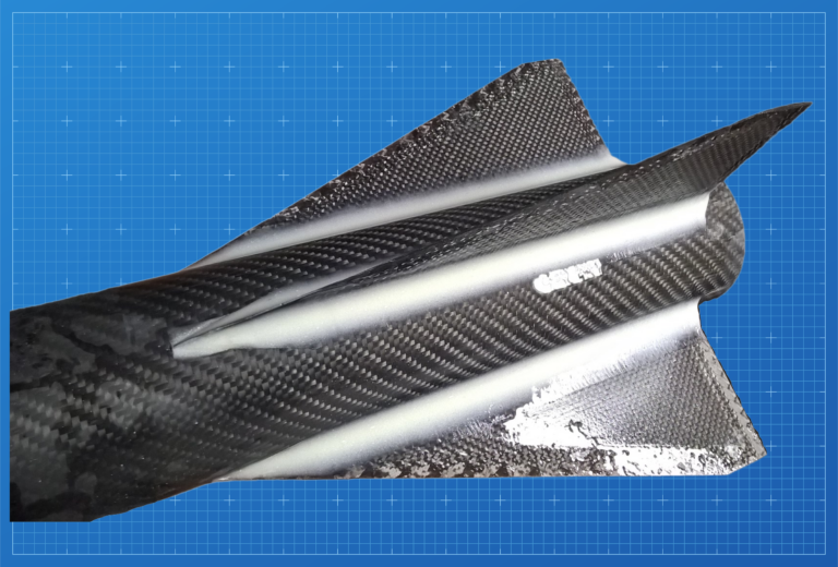
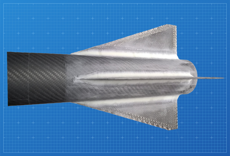
Description | Fins are directly mounted on airframe and four fins are separated by 90 degrees. |
Additional Support / Strength |
|
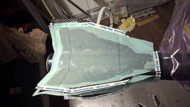
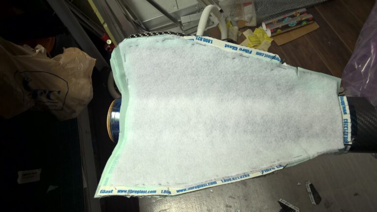
Comments | Basic version: ‘no compression’ layup – fiber sheets are epoxy infused and left to cure. For best results adding a layer of peel-ply to reduce epoxy pooling and runs and slightly better surface finish. Advanced version: full atmospheric compression layup – using vacuum bagging. |

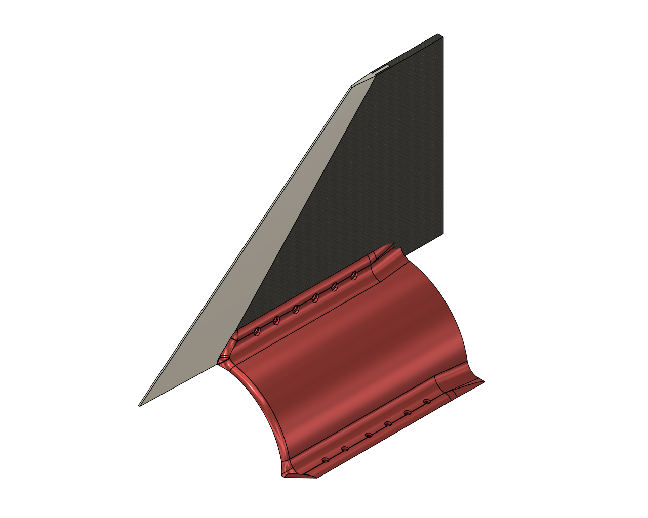
Description | Concept here is to use a combination to techniques as well as mix the construction materials together. Option A:
Option B:
|
Strength Notes | Concern with this design is that the aluminum leading edge could sheer away / break at the bonding interface. |
Advantages | Best of both worlds – combining the lightweight NHC as the fin core and then strengthening the leading edges with fully profiled aluminum. |
Disadvantages | Complex design that will require completely custom CNC work holding to manufacture the leading edges |
Weight |
|
Cost |
|
Application | Suitable for all construction techniques |