The vision: Remove the barrier to flying min-diameter rockets
We should start with the obvious – what defines a min-diameter rocket?
A min diameter rocket can be defined by one criteria: the inside diameter of the sustainer airframe is equal to the outside diameter of the motor. There is no ‘motor mount or gap or any significant gap between the motor and the airframe.
This gap will allow for the fins to pass through the airframe and mounted on the motor-mount and provides significant mounting strength advantages for the fins.
So the biggest challenge with constructing a min diameter rocket is mounting the fins on the airframe since there is no gap between the airframe and the motor.
Strength and or stiffness is THE key design criteria - any design that is listed as RED below will be seen as inadequate.
Weight must or should be low of a given design since the key objective of a min-diameter rocket is to fly fast and high, thus a lower overall weight will result in a higher the power-to-weight ratio and a better performing rocket. We also want the weight to be as far forward / towards the nose cone as possible to ensure optimal rocket stability.
Adding more material will likely result in a stronger and stiffer component but will add weight - so the balance needs to be found where we have a strong but also light component.
Precision is key in the sense that we want fins the be perfectly aligned / parallel to the airframe and each fin perfectly symmetrical - a slight misalignment will impart an aerodynamic force that will add stress to the fins and fin mounting and cause the rocket to spin. Fin canting to induce spin should be a calculated parameter and not random construction artifact. The same logic applies to the fin profile - where we want fins to be perfectly symmetrical as it relates to bevels and aero profiles.
Tolerances of +- 0.001"
An optimal end-user experience is key in the sense that this projects vision is to reduce the construction complexity of a min-diameter rocket - if the construction process is complex then we fail on delivering on this key vision.
Simple end-user mounting experience - this is ultimately the vision - breaking down the barrier to min-diameter rockets - making it easier to fly fast and high.
The Complex Shapes criterion is trivial in a way but still good to consider - since a construction technique that allows us to create fins with complex aerodynamic profiles that are precise and symmetrical will yield a higher performing rocket.
Aesthetics is important in the sense that a rocket needs to look cool 🙂
Cost relates to the end-user cost - if the end-user can have all of the above criterion met at a low cost then this is a viable product.
The following list presents various techniques to construct a min diameter rocket or more specifically how to mount fins to the airframe – where each technique presents more complexity
Each technique will be evaluated against the listed design criteria.
It must be noted that each criterion is subjective and must be evaluated in the context of a rocket accelerating hard and reaching MACH speeds
Fins are cut from composite material (fiberglass or carbon fiber) in desired shape.
Fin leading and trailing edges are beveled by hand on a belt sander or other method.
Fin-alignment jig is used to mount fins onto airframe – fins are epoxied to airframe.
A fillet of strengthened epoxy is added on either side of each fin to create a greater bond between the fins and airframe.
This is a really simple construction but fails in a number of the design criteria.
Strength being the key failure point – in the context of a rocket going Mach speeds. This type of construction will most likely be fine a lower speed.
Multiple layers of fiber cloth – most likely carbon fiber are added in a strand layup orientation that provides maximum strength parallel to fin tips, i.e. a tip-to-tip layup.
This fiber cloth layup is repeated between each fin.
If done correctly this will create an extremely strong and stiff construction.
Advanced process that will need knowledge of vacuum bagging layup and the necessary equipment.
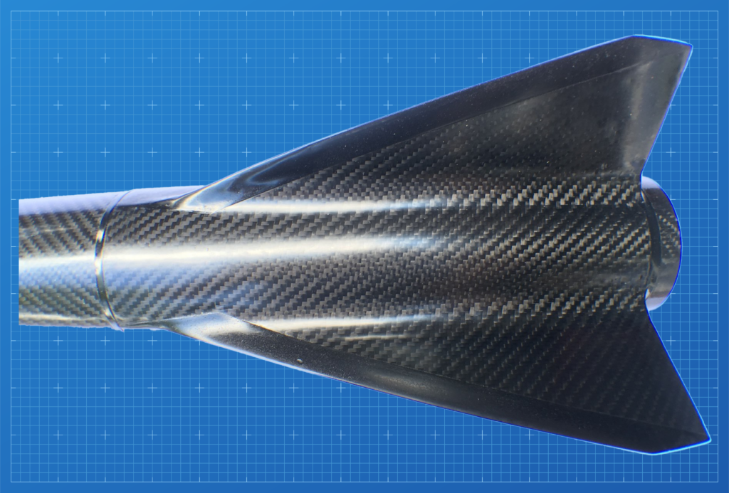
Creating a single piece ‘fin assembly’ that slips onto the airframe or the motor.
At larger scale making a single piece slip on fin assembly is non-trivial – options include:
3D printing the fin assembly has limitations related to size and strength. The chosen 3D print material and 3D printing technology will dictate the strength and size limitations.
FDM printing material has come a long way and there are advanced materials available that includes carbon or glass reinforcement.
However these materials do not allow for the strength and stiffness required to successfully achieve MACH flights.
Advanced resin materials such as Form Labs ‘Rigid 4000’ or ‘Tough 1500’ are strong materials and a printer such as the From 4 or Form 4 L can produce tollerances in the 0.001″ range.
Unclear as to how stiff the material would be as it relates to fin flutter.
Selective Laser Melting (SLM) or Direct Metal Laser Sintering (DMLS) 3D Printing will allow printing using aluminum power or other exotic metals such as titanium and will result an extremely strong and light component.
However the cost of this for the hobbyist is prohibitive.
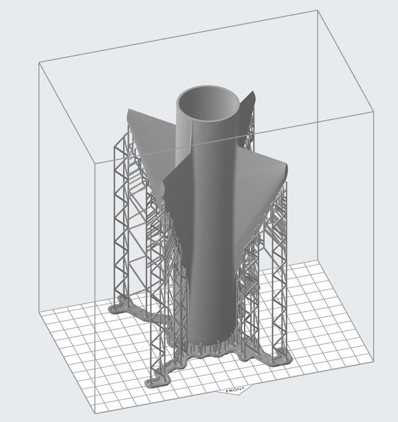
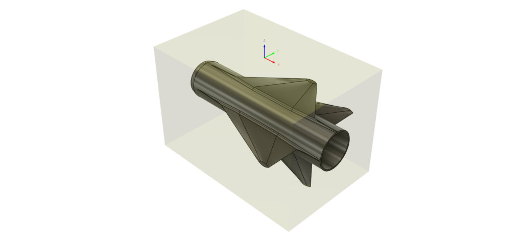
The concept here is to mill the fin assembly from a single block of metal such as aluminum.
This would be a multi-stage milling operation – where each side is milled separately so work holding will be a big consideration.
The final step would be to remove the center core of the piece on a lathe.
This is definitely possible but practically impossible for amateur rocketry unless one owns a CNC mill that would have the XYZ dimensions required to process a larger fin assembly as well as a lath (CNC or manual) to bore out the core.
So how to make this easier and meet all the listed design criterion? Taking a fin-assembly and deconstructing it – breaking it into modular components that can be bolted on / epoxy needed – but still retain the stiffness and strength provided by carbon fiber tip-to-tip.
We will briefly review the first three construction techniques and evaluate against the design criterion.

Construct the fins and inter-fin ‘brackets’ using aluminum plate.
Add bevels to leading and trailing edges of the fins.
Bend the brackets to fit over the airframe with edges that will allow fins to be bolted on. Bending or rolling the brackets to follow the shape of the curved airframe and also add the fin edge interfaces are not trivial without equipment or tools to create these precision shapes.
This type of interlocking construction will be extremely strong and stiff and will also be capable of withstanding high aero heating.
The nature of the material used will not allow for creating complex aerodynamic shapes – simple straight edged bevels.
3D print the fins and or the inter-fin brackets – this might be a good option but likely not meet the strength criteria even if using advanced 3D print materials such as resin.
Metal 3D printing is an option but will likely not be cost effective.
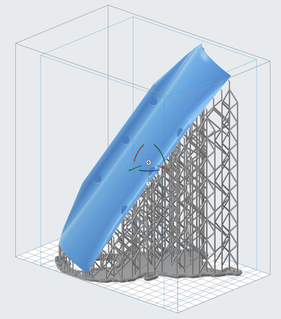
Mill each component, fins and brackets, from aluminum stock using a CNC mill.
Using this process will meet all the design requirements but might not be cost effective if compared to the compression molding technique.
Further investigation will be needed to validate the cost.
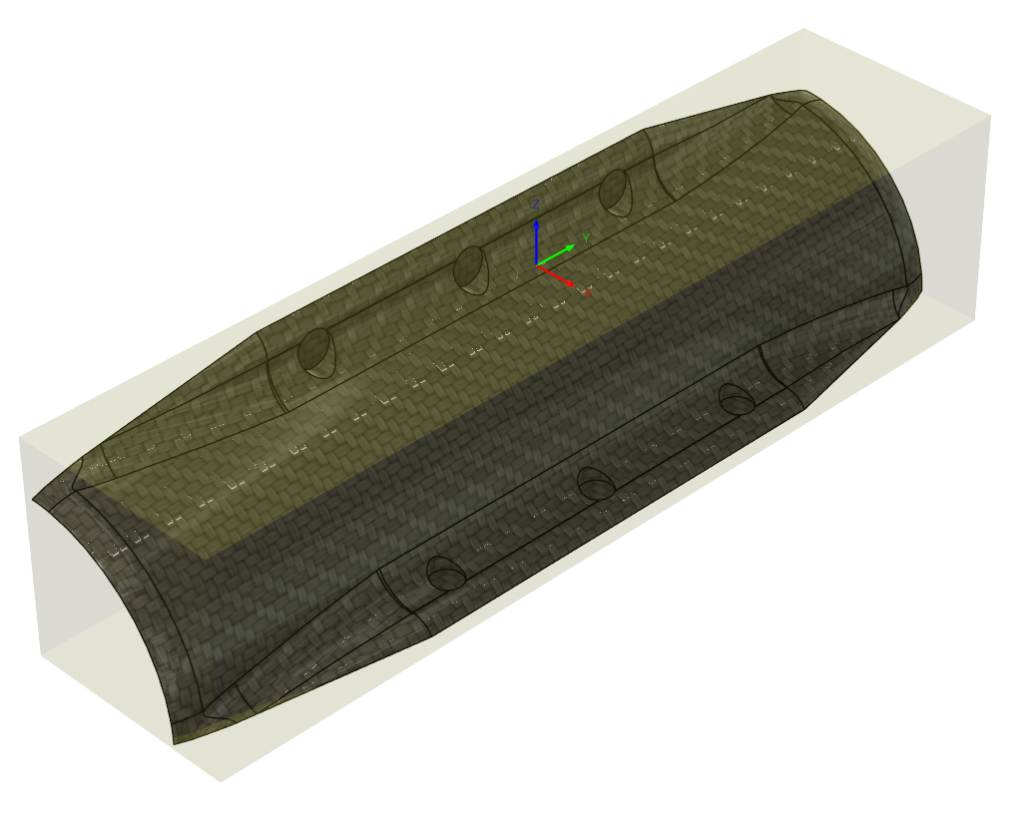
What is ‘Compression Molding’: It is a process where a negative or mirror image is created of a part (the part to be created) and this mirror is the mold – this is best illustrated in the images below.
Compression mold tools will comprise of two or more parts which, when closed together, will leave a cavity where the component will be formed, in almost all circumstances the mold will be in a ‘block’ like format to provide strength and make the clamping or compression process practical.
Compression Molding vs. Forged Carbon Molding:
Forged carbon fiber is the term that has be adopted to describe short or ‘chopped’ strands of carbon fiber that are compression molded in a multi-part mold to create strong solid geometries that would not be practical using conventional composite processes.
There are two fundamental approaches to creating a forged carbon part, one is to use a pre-impregnated (prepreg) chopped tow material and mold this under heat and pressure, the other is to use a dry fiber and liquid resin system and mold under pressure but without heat.
Components manufactured with this method will have fully molded faces, can have varying wall thicknesses, and will provide excellent mechanical performance that can be used in place of metals to reduce weight in many applications.
How will we meet each of the defined design requirements – in the context of using Compression Molding / making the fin assembly components from forged carbon fiber.
Chopped carbon or short strand carbon tow
For the brackets: two layers of 3K 2×2 carbon twill with long fiber orientation, parallel too rocket front/back and perpendicular to fin tips.
Fins bolted to brackets with three stainless steel barrel nuts.
Once assembled onto airframe or directly on motor the whole assembly is also epoxied together.
Strength testing: will be completed once a full modular fin assembly is produced. Also a full MACH 1.9 flight will be performed to test structure in real flight conditions.
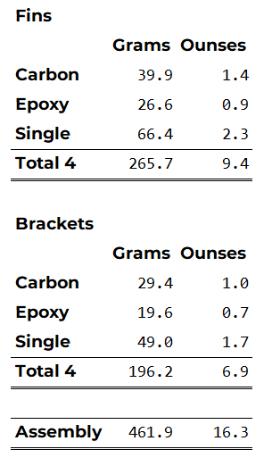
Weight of the final forged carbon fin assembly is only relevant if compared to ither construction techniques that produce similar strength characteristics, such as the aluminum plate modular assembly or the CNC milled modular assembly.
We do not yet have reference data on these two assemblies so will present the weight of the forged carbon brackets and fins individually and as a compete assembly.
Production resin molds as well as CNC aluminum molds will be produced with +-0.001″ tolerances.
Actual measurements will be provided here as well as a cert with actual dimensional accuracies for each manufactured component.
The user-experience will be:
Instructional videos will be provided.
The nature of the forged carbon fiber mold component construction method will allow for any complex shape to be made.
Refer to the Technical Data pages for more information.
Limited production runs will be released, and cost is under review as we complete development.
Additional sizes coming as well – initial size for a 3″ airframe. Future: