

This is a tricky question since for most high-power rocket flights that accelerate beyond MACH 1, the rocket will only be in this flight regime for a relatively short period of time compared to the rest of the flight. So for best or optimal performance it might make sense to design for the subsonic region. For more powerful Level-3 rockets that accelerate really hard and exceed MACH 2 or even MACH 3 it will probably make sense to optimize the design for supersonic speed as it relates to the aerodynamic profile, the fins strength and stiffness.
YES the current Fin Assembly bevel design is a “hybrid” shape that is not optimized for any speed. It’s not rounded for subsonic flow, and its thickest point is in the wrong place for supersonic flow (theoretically)
The Reality: From all the high-power rockets that I have seen the fins are rarely optimized or never optimized for supersonic flights. People will just round the edges or shape some form of triangular beveled edge and call it good – then send it!
Why is there no supersonic optimized fin assembly version?
There could be in the future – creating the design and then more specifically manufacturing the final product is a big investment. The 4inch assembly will likely be optimized for supersonic flights.
Why should or shouldn’t a rocket fins leading edge bevel run from the fin leading edge to the quarter chord line?
That’s an excellent question, as it gets to the heart of fin design for different flight speeds.
The short answer is: it generally shouldn’t.
You are correct to link a fin’s bevel to a specific chord line, but for a high-speed rocket, the quarter-chord (25%) line is the wrong one.
Here is a detailed breakdown of why this is the case and the difference between the two designs.
The Supersonic Fin: Bevel to 50% Chord
For rockets intended to break the sound barrier, the primary goal is to minimize wave drag. This is the intense drag created by the shockwaves the rocket generates.
To do this, you use a specific shape called a double-wedge or diamond airfoil.
So, for a supersonic rocket fin, you should bevel the leading edge in a straight line to the 50% chord line to create a diamond profile.
The Subsonic Fin: Thickest at 25% Chord
The quarter-chord (25%) line you mentioned is the king of subsonic flight (like model rockets, small drones, or airliners).
| Scenario | Bevel/Shape | Why? |
|---|---|---|
| SHOULDN'T run to 25% Chord | A sharp bevel to the 25% mark is a "hybrid" shape that isn't optimal for any speed. It's not rounded for subsonic flow, and its thickest point is in the wrong place for supersonic flow. | |
| SHOULD run to 50% Chord | For Supersonic Rockets. A straight bevel from a sharp leading edge to the 50% chord line creates a double-wedge profile. | This is the standard, low-drag design for supersonic flight. It minimizes wave drag by creating efficient oblique shocks. |
| SHOULD be thickest at 25% Chord | For Subsonic Rockets. A rounded leading edge with the thickest point at the 25% chord line creates a traditional airfoil. | This is the standard, low-drag design for subsonic flight. It prevents flow separation and turbulence.4 |
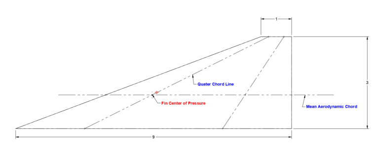
The Quarter Chord Line is an imaginary line that runs along the span of a rocket fin (from its root to its tip) connecting all the points that are 25% of the way back from the leading edge.
In other words, if you measure the chord length (distance from the leading edge to the trailing edge) at any point on the fin, the 25% mark of that measurement will fall on the quarter chord line.
The quarter chord line isn’t just a random geometric measurement; it is arguably the most important reference line in subsonic aerodynamics for stability.
Its entire significance is tied to one critical concept: the Aerodynamic Center (AC).
It’s the “Magic” Point for Pitching Moment:
As a rocket fin flies through the air, it creates lift. This lift also creates a twisting force, or a pitching moment, that tries to make the fin (and thus the rocket) tumble.
For a typical fin at subsonic speeds (below the speed of sound), the Aerodynamic Center is the one point on the fin where this pitching moment does not change, regardless of the rocket’s angle of attack.
This “magic point” is located on the quarter chord line.
It Makes Stability Calculations Possible:
Because the pitching moment is stable at the quarter chord, engineers can simplify all the complex aerodynamic forces (lift, drag, and moments) acting all over the fin into two simple things:
A single lift force acting at the Aerodynamic Center (i.e., on the quarter chord line).
A single, constant pitching moment also acting at that same point.
This massively simplifies the math required to determine if a rocket will be stable.
It’s How You Find the Center of Pressure (CP):
To find the rocket’s overall Center of Pressure (the single point where all aerodynamic forces are balanced), you must first find the CP of each component (nose, body, and fins).
For the fins, the fin’s individual Center of Pressure is located on the quarter chord line (specifically, at the quarter chord point of the fin’s Mean Aerodynamic Chord).
In short, the quarter chord line is the key reference used to locate the fin’s Aerodynamic Center, which is the stable point used for all rocket stability calculations in subsonic flight.
Note on Speed: This 25% rule is for subsonic flight. As a rocket breaks the sound barrier and goes supersonic, the Aerodynamic Center shifts backward from the 25% quarter chord line to near the 50% mid-chord line.
Here’s a breakdown of the Mean Aerodynamic Chord and its relationship to a rocket fin’s root and quarter-chord line.
First, let’s define the key terms:
Chord: An imaginary straight line connecting the leading edge (front) and the trailing edge (back) of an airfoil, like a fin.
Fin Root Chord (Cr): This is the specific chord length of the fin where it attaches to the rocket’s body tube. It’s the “base” of the fin.
Fin Tip Chord (Ct): This is the chord length at the very end, or “tip,” of the fin. For a simple tapered fin, this will be shorter than the root chord.
Quarter Chord Line: This is an imaginary line that runs along the fin’s span, connecting the points that are 25% of the way back from the leading edge at every point along that span. This line is aerodynamically important because, for most airfoils at subsonic speeds, the aerodynamic center (the point where the fin’s pitching moment doesn’t change with the angle of attack) is located very close to this 25% chord point.
The Mean Aerodynamic Chord (MAC) is a single, imaginary chord that represents the average aerodynamic properties of the entire fin.
Think of a fin that tapers from a wide root to a narrow tip. The lift and drag forces are distributed unevenly across its entire surface. Calculating this is complicated. The MAC is a powerful simplification: it’s the chord of a non-tapered, rectangular fin that would have the same total aerodynamic force (like lift) and the same pitching moment as your actual, tapered fin.
In rocket stability analysis, you treat the entire fin’s aerodynamic force as if it acts at a single point. This point is called the Center of Pressure (CP) of the fin, and it is located on the Mean Aerodynamic Chord.
The relationship is all about simplifying a complex 3D fin into a single 2D profile for stability calculations.
MAC vs. Root Chord: The Root Chord is a simple, physical measurement at the fin’s base. The MAC is a calculated, conceptual average chord that represents the entire fin. For a simple trapezoidal fin, the MAC’s length is calculated using the root chord (Cr) and the tip chord (Ct).
MAC vs. Quarter Chord Line: This is the most critical relationship for stability.
The Quarter Chord Line shows you where the 25% chord point is all along the fin’s span.
The Mean Aerodynamic Chord (MAC) also has its own quarter-chord point (25% of its own length).
The Center of Pressure for the entire fin is located at the quarter-chord point of the Mean Aerodynamic Chord.
In short, you first find the MAC (both its length and its position on the fin) to represent the whole fin. Then, you find the 25% point of that MAC to find the fin’s overall Center of Pressure. This point is then used with the rocket’s Center of Gravity to determine if the rocket will be stable in flight.
How do you calculate the distance between the fin Root Cord line and the mean aerodynamic chord line?
(Google Gemini Pro Credit)
Calculate the rocket fin Spanwise Distance for the mean aerodynamic chord when Cr=9, Ct=1, S=3
Python
# Define the given variables
Cr = 9 # Root Chord
Ct = 1 # Tip Chord
S = 3 # Span
# Calculate the Spanwise Distance (y_MAC)
y_MAC = (S / 3) * (Cr + 2 * Ct) / (Cr + Ct)
print(f"Cr = {Cr}")
print(f"Ct = {Ct}")
print(f"S = {S}")
print(f"Spanwise Distance (y_MAC) = {y_MAC}")
Cr = 9
Ct = 1
S = 3
Spanwise Distance (y_MAC) = 1.1
The rocket fin’s spanwise distance for the mean aerodynamic chord ($y_{\text{MAC}}$) is $1.1$.
This value tells you how far out from the rocket’s body (the fin root) the mean aerodynamic chord is located.
Here is the step-by-step calculation using the standard formula.
The fin design of choice is a clipped delta.
Why clipped delta?
Easy to manufacture and in the chosen Root/Simi-Span/Tip configuration does provide slight performance advantages over a Swept Tapered Delta.
Performance vs. other shapes:
For supersonic rockets, the Clipped Delta and Swept Delta profiles generate less drag than the other shapes.
Looking at sounding rocket designs the Taper Swept Delta is prevalent on a number of rockets – image example below.
The below table presents data from various Clipped Delta designs.
931 represents:
Where:
Open Rocket was used to run various simulations – keeping everything in the rocket the the same and only modifying the fin configurations – ratios as well as count.
The 931 ratio performs the ‘best when compared to other Clipped Delta configurations – the pure Delta does perform better but the sharp tip does present manufacturing complexities and will be prone to damage during flight / landing.
Realistically the difference between the performance is negligible.
Fin Bevels
Leading and trailing edge bevels extend to the 1/4 Quarter Cord lines.
4 Fins vs. 3 Fins
Constructing a rocket with 4 fins does add more complexity – it is one more fin that must be aligned and attached and if traditional construction methods are used (such as tip-to-tip) carbon layup then the added fin and surface add significant more effort.
However – with the proposed modular forged carbon construction this becomes irrelevant.
Reducing the inter-fin area does make compression molding a bracket easier.
The additional bracket will add additional clamping force.
Fin Flutter calculations were done on this 931 Clipped Delta configuration using the Martin Method and the Fin Flutter Calculator that can be found here:
https://github.com/jkb-git/Fin-Flutter-Velocity-Calculator
The below calculations use the max acceleration and altitude values from the above table – launching from FAR in California. First calculation assumes a Tip-to-Tip construction and the second use NO Tip-to-Tip since this modular forged carbon construction is technically NOT a tip-to-tip construction and will not have the same strength characteristics.
The non-tip-to-tip calculation (assuming an average fin thickness of 0.23″ – 0.25 at the chord root and 0.125 at the tip) shows a safe margin or 29.8%
A quick analysis was one using three different Swept Delta configurations – comparing the Open Rocket performance data against the above / chosenn 931 Clipped Delta configuration – the 8.103.1 configuration present slight improvement over the 931 Clipped Delta – but not enough to adopt this design.